
Back to 12 Switch + 2 Plug
Specs, wiring & warranty — 12 Switch + 2 Plug
Technical specifications
| Colours | Black, White, Blue & Grey |
|---|---|
| Power Source | AC 240V 50Hz |
| Module | 12 (12 Switches & 2 Plugs) |
| Max Load (Per Switch) | GLS & Halogen Max.200W, |
| Max Load (High load Switch) | AC Up to 2000W (~2 Ton AC with EER > 3.5) |
| Max Load (Plug) | Max.500W |
| Self-Consumption | ~2.4W |
| Wireless Standard | IEEE 802.11 b/g/n |
| Operating Temp | -10°C to +55°C |
| Dimension | 247mm x 88mm x 43mm |
| Enclosure Material | ABS (FR Grade) |
| Net Weight | 0.5kg |
| Remote control distance | 25 ft |
Wiring drawing

| Terminal | Meaning |
|---|---|
| N | Neutral |
| P1 | Phase 1 UPS/EB |
| L1 - L4 | Lights 1-4 |
| P2 | Phase 2 EB |
| L5 - L9 | Light 5-9 |
| P3 | Phase 3 |
| H1, H2, H3 | High-Load |
| E1 & E2 | Earth |
| 1 & 2 | Socket |
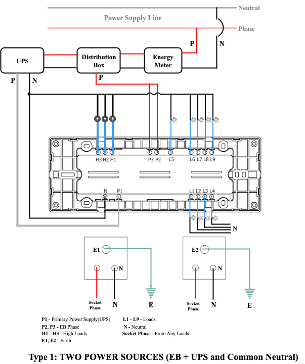
- Type 1: Two Power Sources (EB + UPS and Common Neutral): The phases for EB and UPS will remain separate. The neutral line will be common for both EB and UPS. In the above scenario, the phase and neutral connections will be as follows: The UPS phase is connected to P1, providing power to the device and the first four loads (L1, L2, L3, and L4). The EB phase is connected to P2, supplying power to the five loads (L5, L6, L7, L8 and L9). Establish a loop connection from the P2 phase to the P3 phase to create a common phase line, supplying power to three loads (H1, H2 and H3). The phases of sockets 1 and 2 can be from any two load terminals or the primary power supply, and an earth point (E1 and E2) must be connected for each plug. The common neutral will be connected to N.
- Type 2: Common Phase (EB or UPS and Common Neutral): The P1, P2 and P3 phases share the same phase line, either from the EB or UPS. The P1 phase is the primary power supply. Establish a loop connection from the P1 phase to the P2 phase and P3 phase to create a common phase line. In this scenario, the phase and neutral connections will be as follows: The EB or UPS phase is connected to P1, providing power to the device and the first four loads (L1, L2, L3, and L4). The P1 phase is looped to P2, supplying power to the three loads (L5, L6, L7, L8 and L9). The P1 phase is looped to P3, supplying power to the three loads (H1, H2 and H3). The phases of sockets 1 and 2 can be from any two load terminals or the primary power supply, and an earth point (E1 and E2) must be connected for each plug. The common neutral will be connected to N.
- Type 3: Common Phase(EB or UPS) but different Load Capacity: The P1, P2 and P3 phases share the same phase line but have different load capacities, such as 6A and 16A, respectively. The P1 phase is the primary power supply. In this scenario, the phase and neutral connections will be as follows: P1 and P2 are responsible for 6A load variants. The EB or UPS phase is connected to P1, providing power to the device and the first four loads(L1, L2, L3, and L4).P2, providing power to the device and the five loads(L5, L6, L7, L8 and L9) P3 is responsible for 16A load variants. The EB phase is connected to P3, providing power to the three loads ( H1, H2 and H3). The phases of sockets 1 and 2 can be from any two load terminals or the primary power supply, and an earth point (E1 and E2) must be connected for each plug. The common neutral will be connected to N.
- Type 4: Different Phase and Different Neutral: P1, P2 and P3 have different phases: one from the generator or solar, and the other from the EB. The neutral line will be different for both the generator/solar and the EB. In this scenario, the phase and neutral connections will be as follows: The generator phase is connected to P1, providing power to the three loads (L1, L2, L3 and L4). The EB phase is connected to P2 and P3. P2, providing power to the device and the five loads (L5, L6, L7, L8 and L9) whereas, P3, providing power to the device and the three loads (H1, H2 and H3). The phases of sockets 1 and 2 can be from any two load terminals or the primary power supply, and an earth point (E1 and E2) must be connected for each plug. Separate neutrals are connected to P1, P2 and P3.
- Type 5: Additional Customization for High Load Output Using External Relay (Common Neutral): The phases for EB and UPS will remain separate. The neutral line will be common for both EB and UPS. In the above scenario, the phase and neutral connections will be as follows: The UPS phase is connected to P1, providing power to the device and the first four loads (L1, L2, L3, and L4). The EB phase is connected to P2, supplying power to the five loads (L5, L6, L7, L8 and L9). Establish a loop connection from the P2 phase to the P3 phase to create a common phase line, supplying power to three loads (H1, H2 and H3). The phases of sockets 1 and 2 can be from any two load terminals or the primary power supply, and an earth point (E1 and E2) must be connected for each plug. The common neutral will be connected to N. To externally control high loads through an existing power switch (e.g., from L9, 6A), add a 40A relay for external supply control. In the above scenario, the connections for the relay will be as follows: The phase for the relay is from L9. The relay IN is directly connected from the DB phase. Then the relay OUT is connected to the AC load. The common neutral (N) will be connected for both the relay and the AC load. Note: Implement this solution only with accurate information from the official technical support team.
In the box
- Touch Switch 12S2P × 1
- Remote × 1
- Console Screws × 4
- Instruction Manual × 1
Warranty
3 years
- Iotics Technology Private Limited undertakes to replace or repair, at its discretion, products should they become defective solely as a result of any manufacturing defects for a period of 3 years from the date of purchase.
- The guarantee will be valid only if installation procedures / maintenance are carried out by a qualified professional electrician and the product has been used in a specific way and for the specified purposes as mentioned in the user's manual.
- Loss or damages resulting from unauthorized adaptations/adjustments/tampering/improper installation of the product are not covered.
- Accidental/Physical/water damage and damage due to high voltage burnouts are out of the purview.
- The manufacturer takes no direct, indirect or any type of consequential liability of whatsoever nature under any condition, of customer's appliances functioning or malfunctioning of his/her appliance by or after buying the product.
- The guarantee does not extend to cover consequential loss, damage or installation costs arising from the defective product.
Safety
- Do not install the device without turning OFF the main power supply.
- Do not connect the glass panel without turning OFF the main power supply.
- For Loads L1 to L9, do not connect loads greater than 6A. Each light switch is rated up to 6A resistive only.
- For loads H1, H2 & H3, do not connect loads greater than 16A. Each High Load switch is rated up to 16A resistive only.
- For Socket, Do not connect loads greater than 6A. Socket is rated up to 6A resistive only.
- Take extra precaution while connecting phase and neutral wires to the device and the load.
- Do not connect loads in series or in parallel to one 6A light switch. Only connect a single light or single fan load to each 6A switch.
- Only a single load (6A) with a maximum of 40W is supported in cases of LED & CFL fittings. Anything more may weld the switch contacts and leave the load in a permanently ON state.
- 12V and 24V power supply-based LED light strips are NOT supported in 6A light switches. 240V Mains Voltage LED Strip Lights are supported in 6A light switches.
- Relay - 5 Amps - Res.1000W / Ind.300W
- Relay - 16 Amps - Ind.2000W