
Back to In-wall 4 Switch
Specs, wiring & warranty — In-wall 4 Switch
Technical specifications
| Colours | Black |
|---|---|
| Power Source | AC 240V 50Hz |
| Max Load (Per Switch) | GLS & Halogen Max.200W; LED & CFL Max.40W |
| Max Load (High load Switch) | AC Upto 2000W (~2 Ton AC with EER > 3.5); Chandelier Max.400W (GLS & Halogen) |
| Self-Consumption | ~1.6W |
| Operating Temperature | -10°C to +55°C |
| Dimension | 100 mm x 51 mm x 21 mm |
| Enclosure Material | PVC Heat Shrink Sleeve |
| Net Weight | 0.095 kg |
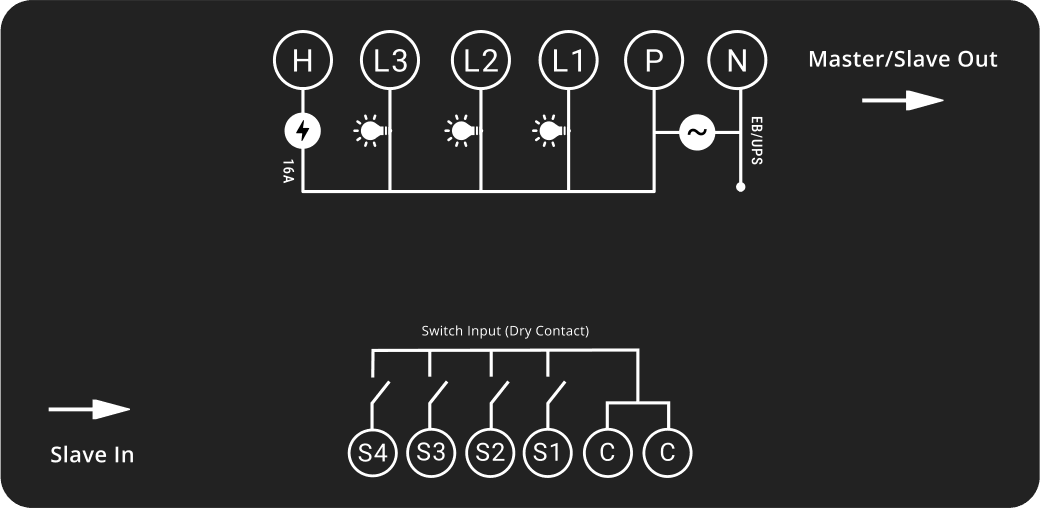
Wiring drawing

| Terminal | Meaning |
|---|---|
| P | Phase (EB/UPS) |
| N | Neutral |
| L1, L2, L3 | Light loads, 6A each |
| H | High load, 16A |
| C | Switch common |
| S1–S4 | Wall switch 1–4 |
- P powers L1, L2, L3 and H.
- Connect the UPS or EB phase to the P terminal.
- The wall switches are dry contacts: never connect 230V AC to the switches or to the C and S terminals.
- Supported metal box sizes: 4M, 6M, 8M, 12M and 16M.
- For master and expansion module combinations, do not join the C terminal of the master module to the C terminal of an expansion module.
In the box
- Inwall switch 4S × 1
- Instruction Manual × 1
- Module Connectors × As per switch combination
Warranty
3 years
- Iotics Technology Private Limited undertakes to replace or repair, at its discretion, products should they become defective solely as a result of any manufacturing defects for a period of 3 years from the date of purchase.
- The guarantee will be valid only if installation procedures / maintenance are carried out by a qualified professional electrician and the product has been used in a specific way and for the specified purposes as mentioned in the user's manual.
- Loss or damages resulting from unauthorized adaptations/adjustments/tampering/improper installation of the product are not covered.
- Accidental/Physical/water damage and damage due to high voltage burnouts are out of the purview.
- The manufacturer takes no direct, indirect or any type of consequential liability of whatsoever nature under any condition, of customer's appliances functioning or malfunctioning of his/her appliance by or after buying the product.
- The guarantee does not extend to cover consequential loss, damage or installation costs arising from the defective product.
Safety
- Do not install the device without turning off the main power supply.
- For Loads L1 to L3, do not connect loads greater than 6A. Each light switch is rated upto 6A resistive only.
- For Load H, Do not connect loads greater than 16A. Each High Load switch is rated upto 16A resistive only.
- Take extra precaution while connecting phase and neutral wires to the device and the load.
- Do not connect AC supply to the switches which are connected to the control terminals C and S.
- Do not connect loads in series or in parallel to one 6A light switch. Only connect a single light load to each 6A switch.
- Only a single load (6A) with a maximum of 40W is supported in cases of LED & CFL fittings. Anything more may weld the switch contacts and leave the load in a permanently ON state.
- 12V and 24V power supply-based LED light strips are NOT supported in 6A light switches. 240V Mains Voltage LED Strip Lights are supported in 6A light switches.
- Relay - 5 Amps - Res.1000W / Ind.300W
- Relay - 16 Amps - Ind.2000W